P-NET is an international fieldbus standard (IEC 61158 type 4). The physical layer of P-NET is based on EIA RS485. (Read more…)
P-NET using RS485 allows for two different installation techniques: ‘P-NET’ and ‘4-WIRE P-NET’.
The same rules concerning cable lengths, number of nodes, communication speed etc, apply to both installation variants.
With 4-WIRE P-NET, both communication and power supply are included in the same bus cable.
Connecting P-NET modules in the ‘traditional’ way, establishes a communication link between a number of individual nodes, with each having its own power supply.
By using the appropriate adapters and the correct installation techniques, P-NET and 4-WIRE P-NET networks can be mixed within an installation and still maintain a fully transparent system.
P-NET can be installed using a number of different techniques and topologies.
Select one of the topologies below for further information

P-NET Ring Topology
The P-NET cable is connected to a number of devices in a way that forms a physical ring. Each device on the ring is connected using the same principle.

P-NET Bus Topology
All nodes between the two termination nodes are connected in the same way as modules in P-NET ring topology.

P-NET Redundancy
P-NET redundancy provides an additional communication network path between a number of M36 clusters.

4-WIRE P-NET Topology
4-WIRE P-NET is a wiring principle that enables a number of simple devices to be connected by means of a single cable.

P-NET Light-Link
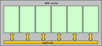
P-NET Light-Link provides an optical communication link for P-NET. Light-Link provides galvanic isolation between each member in a communication chain.
P-NET modules which use the traditional method
– PD 340 Flow Transmitters
– PD 3000 Family
– PD 4000 Controller
– PD 5000 Controller Family
– PD 600 Family (M36), when using BM 002 or BM 010 base modules
– PD 800 Family (M100)
4-WIRE P-NET modules
– PD 681
– PD 600 Family (M36), when using BM 012 base modules
P-NET Light-Link modules
– PD 600 Family (M36)
– PD 800 Family (M100)


