PD340 - Three-phase output signals
- Two-phase counter with error / Counter with up/down
The PD 340 Flow Transmitter – extended version, can be configured to drive 3-phased output signals.
The configuration makes the Flow Transmitter act like a mechanical flowmeter.
The 3-phase output signals may be used in three different modes. Below is a brief overview prior to more comprehensive explanations later in this section:
- Three-phase counter without separate error signal.
- Two-phase counter with separate error signal.
- Counter with up/down signal and separate error signal.
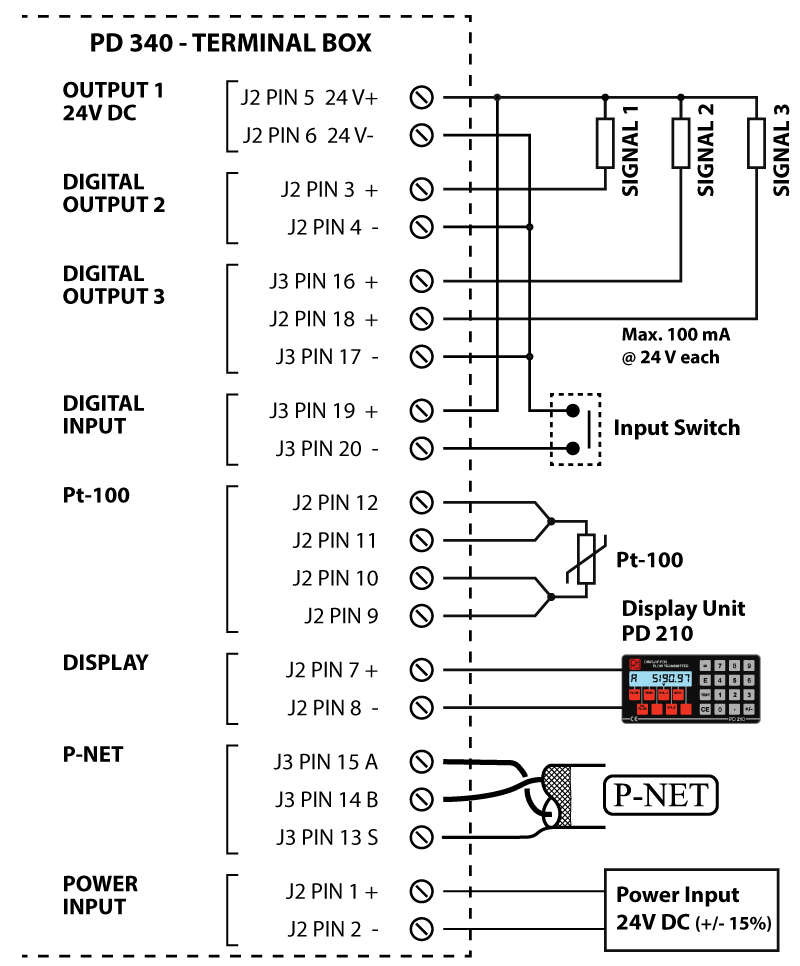
When used for one of the 3-phase output modes, the output signals and the matching options CANNOT be configured or used as described in the previous sections, and the texts on the terminal board lose their original meaning as well.
Instead, the outputs are used as shown in the drawing below. It is universal for all the 3-phase application modes, in terms of the electrical connections for the signals, i.e. Signal 1, Signal 2, Signal 3, respectively.
The operation mode is selected by means of Code2, digit 1. Please refer to the table at the end of this chapter for an overview of the relationship between modes and their corresponding signals and terminal numbers.

3-phase counter without separate error signal
This mode indicates the flow rate by means of 3-phase pulse signals.
The phase sequence indicates the flow direction and the pulse frequency indicates the flow rate. An error in the Flow Transmitter will open the three output signals (high-impedance state).
See the first of the signal diagrams below. In the second diagram, backward flow alters the sequence of the output signals. Apart from the phase sequence, the functionality for backward flow is the same as for forward flow.


2-phase counter with separate error signal
This mode indicates the flow rate by means of 2-phase pulse signals. The error signal is closed circuit during error-free measurement. The phase sequence indicates the flow direction and the pulse frequency indicates the flow rate. An error in the Flow Transmitter will open the three output signals (high-impedance state), i.e. the error signal and both pulse signals. See the first of the signal diagrams below. In the second diagram, a backward flow alters the sequence of the two pulse signals. Apart from the phase sequence, the functionality for backward flow is the same as for forward flow.


Counter with up/down signal and separate error signal
This mode indicates the flow rate by means of 1 pulse signal. The error signal is closed circuit during error-free measurement. The flow direction is indicated by the up/down signal and the pulse frequency indicates the flow rate. An error in the Flow Transmitter will open all 3 output signals (high-impedance state). See the signal diagram below.

Table showing signal mode relationships
The configuration for the Flow Transmitter should adhere to the following example when util-ising the 3-phased output mode.
This configuration is the same for all sizes of the Flow Transmitter:
The Code2 variable (PD 210 display key E7) must be set to X * 8 * * 0 0 0, where X can have the mode values: 6, 7 and 8.
The * indicates that these digits should be configured according to the actual application and working conditions for the Flow Transmitter.
The table shows the function of each signal, depending on the selected mode.
| Mode 1 Simple | Mode 2 2-phase | Mode 3 3-phase | Terminal number |
|
|---|---|---|---|---|
| Code 2 (E7) Digit 1 | 6 | 7 | 8 | |
| Signal 1 | Phase 1 | Error | Phase 1 | 3 |
| Signal 2 | Up/down | Phase 1 | Phase 2 | 16 |
| Signal 3 | Error | Phase 2 | Phase 3 | 18 |
