Info note
PD 602 DPI routing between IP networks
When using PD 602 DPIs, it is often required that the process controller can access data in other DPIs or in other interface modules.
This info note contains a number of examples showing the required configuration of a PD 602 DPI accessing data in another module and how to define the correct route used in the Process-Pascal program.
If the two PD 602 DPIs are located on the same IP network, the configuration and routing is very simple. However, the route and configuration of the DPI becomes a little more advanced if routing between different IP networks takes place via a router or if the IP communication goes via the Internet through firewalls, NAT routers etc.
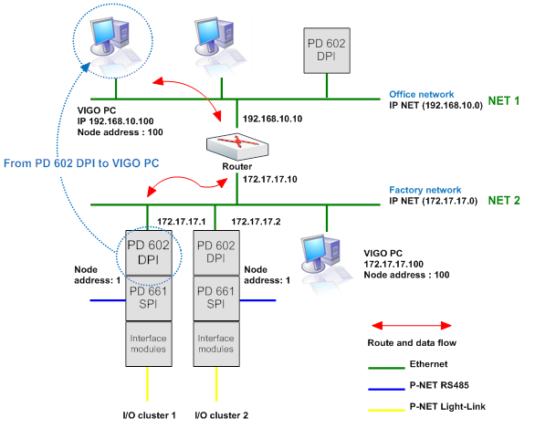
Ethernet example 1:
Ethernet example 1 shows a PD 602 DPI located on the factory network 172.17.17.0 that needs to communicate with a VIGO PC located at the office network 192.168.10.0.
This example shows the configuration of the IPNetTable in the PD 602 DPI that enables the device to access P-NET nodes on another IP network. Please note when using Port 1, the Ethernet port of the module will always use the IPNetTable in the EthernetPort channel.
Configuration of IPNetTable in PD 602 DPI, IP address 172.17.17.1
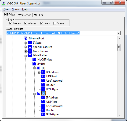
Configuration
Ethernet.EthernetPort.IPNetTable.NoOfIPNets = 2
IPNets[1].IPAddress = 192.168.10.0
IPNets[1].UDPPort = 34378
IPNets[1].UsePassword = False
IPNets[1].Router = NA = 10 (last byte in IP address)
IPNets[1].IPNettype = 1
IPNets[2].IPAddress = 172.17.17.0
IPNets[2].UDPPort = 34378
IPNets[2].UsePassword = False
IPNets[2].Router = 0
IPNets[2].IPNettype = 1
Process-Pascal, variables on P-NET:
AT NET specifies that the declared variable is an external variable located on P-NET. Any access to that variable is performed via the network.
The following parameters (1,2,1,100) specify where the module is located, as seen from the controller.
The first parameter indicates the communication port (Port 1, Ethernet), the following parameters define the Net ID sender, the Net ID receiver, and finally the node address number 100.
Examples of variable declarations, using a net list and a SOFTWIRE clause:
Var
(* Indirect variable to SW 6 in the VIGO PC on net 192.168.10.0 *)
ExtByte: Byte [devicetype:7000] AT NET: (1,2,1,100) SOFTWIRE: 6;
Ethernet example 2:
Ethernet example 2 shows a PD 602 DPI located on the factory network 172.17.17.0. The PD 602 DPI 172.17.17.1 needs to communicate with DPI 172.17.17.2 in I/O cluster 2 on the factory network. In this example there is no need for configuration of the IPNetTable because the two PD 602 DPIs are located on the same network.
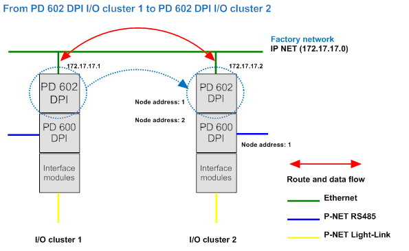
Process-Pascal, variables on P-NET:
AT NET specifies that the declared variable is an external variable located on P-NET. Any access to that variable is performed via the network.
The parameters (1,1,1,2) specify where the module is located, as seen from the controller. The first parameter indicates the communication port (Port 1, Ethernet), the following parameters define the Net ID sender, Net ID receiver, and finally the node address number 2.
Examples of variable declarations, using a net list and a SOFTWIRE clause:
Var
(* Indirect variable to SW 1 in the DPI 172.17.17.2 *)
ExtWord: Word [devicetype:602] AT NET: (1,1,1,2) SOFTWIRE: 1;
Ethernet / P-NET example:
This example shows how to define the route from the PD 602 DPI 172.17.17.1 /172.17.17.2 to the interface module node address 64 using a PD 600 DPI as a gateway.
In this example there is no need for configuration of the IPNetTable because the two PD 602 DPIs are located on the same network.
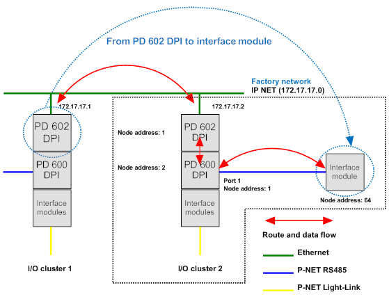
Process-Pascal, variables on P-NET:
From PD 602 DPI in I/O cluster 2 (172.17.17.2 ) to Interface module node address 64
AT NET specifies that the declared variable is an external variable located on P-NET. Any access to that variable is performed via the network.
The parameters (2,2,1,64) specify where the module is located, as seen from the controller (172.17.17.2) in I/O cluster 2. The first parameter indicates the communication port (Port 2, P-NET Light-Link), the following parameters define the node address for the gateway, the port number out of the gateway, and finally the interface module node number 64.
From PD 602 DPI in I/O Cluster 1 (172.17.17.1 ) to Interface module node address 64
AT NET specifies that the declared variable is an external variable located on P-NET. Any access to that variable is performed via the network.
The parameters (1,1,1,2,) specify where the next module in the communication row is located, as seen from the controller (172.17.17.1). The first parameter indicates the communication port (Port 1, Ethernet), the following parameters define the Net ID sender, Net ID receiver, and finally the node address number 2 of the PD 602 DPI in I/O cluster 2.
The total route is thus made up by the parameters: (1,1,1,2) + (2,2,1,64) => (1,1,1,2,2,2,1,64)
Examples of variable declarations, using a net list and a SOFTWIRE clause:
Var
(* 172.17.17.2, Indirect variable to SW 18 in interface module *)
ExtCounter: LongInteger [devicetype:621] AT NET: (2, 2,1,64) SOFTWIRE: 18;
(* 172.17.17.1, Indirect variable to SW 18 in interface module *)
ExtCounter: LongInteger [devicetype:621] AT NET: (1,1,1,2,2,2,1,64) SOFTWIRE: 18;
PD 602 DPI - PD 602 DPI via the Internet
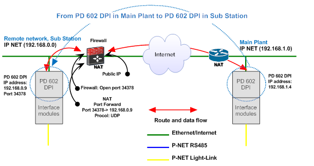
Example:
This example shows a configuration in which two PD 602 DPIs communicate via the Internet.
The DPI in the Main Plant uses the default UDP Port number 34378 “Non Secure UDP” to access the DPI in the Sub Station. Configuration of the IPNetTable is required.
Configuration of IPNetTable in PD 602 DPI, IP address 192.168.1.4
EthernetPort.IPNetTable.NoOfIPNets = 2
IPNets[1].IPAddress = 192.168.1.0
IPNets[1].UDPPort = 34378
IPNets[1].UsePassword = False
IPNets[1].Router = 0
IPNets[1].IPNettype = 1 (IPRange)
IPNets[2].IPAddress = Public IP Address
IPNets[2].UDPPort = 34369
IPNets[2].UsePassword = False
IPNets[2].Router = 1
IPNets[2].IPNettype = 2 (UDPRange)
On a UDPRange network, the complete IP address comes from the IPNetTable entry selected by the NetIndex. The NodeAddress is added to the UDPPort defined in the IPNetTable entry. This configuration is used to access nodes on a remote network through a NAT router. The IPAddress of the UDPRange subnet is the IPAddress exposed to the Internet by the remote NAT router. The router must be configured to translate the incoming UDP port number into the IPAddress of the node to be accessed, and to UDP port number 34378. A separate UDPRange subnet must be used for each remote network to be accessed.
IPNets[2].UDPPort:
The PD 602 DPI uses by default port number 34378 “Non Secure UDP” for communication and this port must in this example be forwarded to PD 602 DP IP address 192.168.0.9 located at the Sub Station. IPNets[2].UDPPort = 34378 – Node address => 34378 – 9 = 34369.
IPNets[2].Router:
The Router field holds the node address of the router.
NAT Router in Main Plant, IP address = 192.168.1.1
IPNets[2].Router = NA (last byte in IP address) => IPNets[2].Router = 1.
ExtRealArrayRec: RealArrayRec [devicetype:602] AT NET: (1,1,2,9) SOFTWIRE: 848;
The last parameter within the brackets defines the node address and if the node address is changed to e.g. 100 (1,1,2,100), the IPNets[2].UDPPort equals 34378 – Node address 100 => Port number 34278.
The node address in the Process-Pascal program is often defined as the number equal to the last byte in the IP address e.g. 192.168.0.9. This is however not mandatory.
If the NAT router doesn’t support Port Address Translation, it is only possible to access a single PD 602 DPI in the Sub Station.
Process-Pascal, variables on P-NET:
AT NET specifies that the declared variable is an external variable located on P-NET. Any access to that variable is performed via the network.
The parameters (1,1,2,9) specify where the module is located, as seen from the controller. The first parameter indicates the communication port (Port 1, Ethernet), the following parameters define the Net ID sender, the Net ID receiver, and finally the node address number 9.
Examples of variable declarations, using a net list and a SOFTWIRE clause:
Type
RealArrayRec= Record
Realvalue: Array[1..4] of Real;
End;
Var
(* Indirect variable to Record at SW 848 in the DPI 192.168.0.9 *)
ExtRealArrayRec: RealArrayRec [devicetype:602] AT NET: (1,1,2,9) SOFTWIRE: 848;
(* Indirect variable to Real SW 850 in the DPI 192.168.0.9 *)
ExtReal: Real: [devicetype:602] AT NET: (1,1,2,9) SOFTWIRE: 850;
Internet Communication
The response time over the Internet is a lot slower compared to the response time over P-NET RS485.
The default setting for EthernetPort.SpecialFeatures.MaxResponseTime is 2 sec. It is therefore recommended that AutoChangeTask is used in all Tasks that access external devices via the Internet to avoid that the program execution in the DPI is locked in the period corresponding to MaxResponseTime in case of transmission errors. MaxResponseTime can often be reduced to 0.3-0.5 sec. and EthernetPort.
Retries can with advantage be adjusted to a number between one and four. The total MaxResponseTime is equal to MaxResponseTime x Retries.
Task Test TIMEDINTERRUPT: 5.0;
Begin
Enable(AutoChangeTask);
Loop
CyclicTask;
ExtReal:= SetPoint; (* Write to external variable *)
RealArrayRec:= ExtRealArrayRec; (* Read external variable *)
TimedTask;
ChangeTask;
End;
End;


